In part one of our technical drawing series we looked at Layout and part 2 explored Labelling and Annotation. You can also select a data separator.

Engineering Drawing Different Types Of Lines And Their Uses Youtube
The indicator is easy to use and very informative.
. This engineering drawing present weld type symbols and fillet weld symbols. Before we get started on any technical drawings lets get a good look at this strange block from several angles. To the right of the price always following it.
Depending on the nature and complexity of a project the floor plan can contain simple or complex information. In a selected screen corner. You can disable unnecessary items of information in the settings.
Though the two types of analysis are not mutually exclusive usually traders will fall into one category or the other. The weld type symbol is typically placed above or below the center of the reference line depending on which side of the joint its on. Learn how to create professional documents and drawings that help you deliver stronger projects in mechanical architecture engineering or construction industries Technical Drawing for Design and Drafting Outline.
As a comment in the upper left corner of the chart. One of the first and most important things forex traders have to learn and master is the two types of market analysis - fundamental analysis and technical analysis. The symbol is interpreted as a simplified cross-section of the weld.
Build your technical drawing skillset in AutoCAD. This is one of a family of three-dimensional views called pictorial drawings. Both fundamental and technical analysis have their unique advantages and disadvantages.
You can select one of the different info line location types. Fillet welding refers to the process of joining two pieces of metal together whether they be. In this part of the technical drawing series we will look at Plans.
It may be that a number of different floor plans are. Figure 1 - A Machined Block. In an isometric drawing the objects vertical lines are drawn vertically and.
The representation of the object in figure 2 is called an isometric drawing.
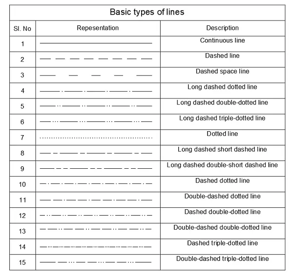
Types Of Line In Engineering No 1 Detailed Guide To Line Types

Standard Engineering Drawing Line Types Line Art Lesson Types Of Lines Different Types Of Lines

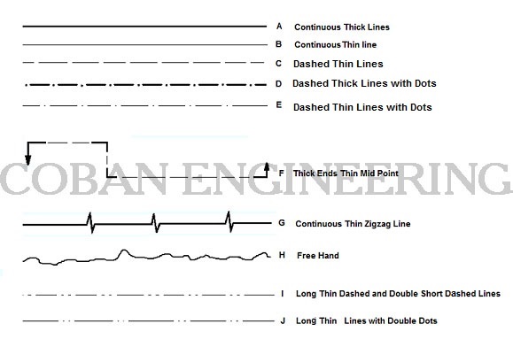
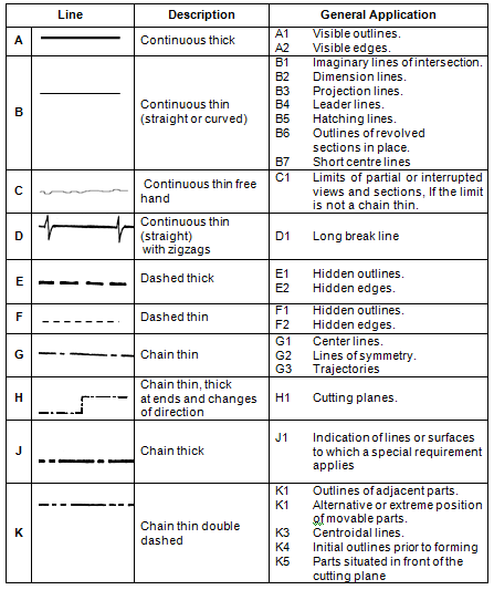
Technical Drawing Standards Line Types
Activity 2a
Technical Drawings Lines Geometric Dimensioning And Tolerancing Definition Of The Drawings Lines Iso Ansi Projected Two View Drawing

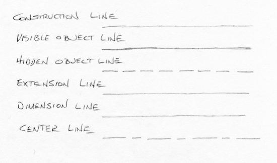
10 Different Types Of Lines Used In Engineering Drawing

Engineering Drawing Wikipedia
Type Of Lines In Technical Drawings
0 comments
Post a Comment